#2268 closed defect (fixed)
icons in library browser get displayed wrong
| Reported by: | Owned by: | Adeel Asghar | |
|---|---|---|---|
| Priority: | high | Milestone: | 1.9.0 |
| Component: | OMEdit | Version: | trunk |
| Keywords: | Cc: |
Description
I created a library in OMEdit (trunk version). Than, I edited this library with an older OMEdit version. Now, the icons in the library browser and the block diagrams get displayed wrong. See attached images.
Attachments (6)
Change History (15)
by , 13 years ago
by , 13 years ago
comment:1 by , 13 years ago
follow-up: 3 comment:2 by , 13 years ago
Maik is one of our students and we are using OpenModelica 1.9.0 beta4+dev (r15969) for teaching. I guess this is the older version he mentioned.
comment:3 by , 13 years ago
comment:4 by , 13 years ago
I guess, the issue occurs using the current trunk version. But to produce the bug, he was using that older version in the middle of his modelling process:
- Create Model with current trunk version (correct displayed icons)
- Edit model with old version (correct displayed icons)
- Edit model with current trunk version (wrong displayed icons)
Am I right?
comment:6 by , 13 years ago
package TestIcon
  package Schnitstelle
    connector Pin
      Real v;
      flow Real i;
      annotation(Diagram(coordinateSystem(extent = {{-100,-100},{100,100}}, preserveAspectRatio = true, initialScale = 0.1, grid = {2,2})), Icon(coordinateSystem(extent = {{-100,-100},{100,100}}, preserveAspectRatio = true, initialScale = 0.1, grid = {2,2}), graphics = {Rectangle(origin = {0,5.46022}, fillColor = {255,0,0}, fillPattern = FillPattern.Solid, extent = {{-99.5319,94.6958},{100.156,-105.616}})}));
    end Pin;
    connector NPin
      Real v;
      flow Real i;
      annotation(Icon(coordinateSystem(extent = {{-100,-100},{100,100}}, preserveAspectRatio = true, initialScale = 0.1, grid = {2,2}), graphics = {Rectangle(origin = {-15.7566,25.429}, fillColor = {0,0,255}, fillPattern = FillPattern.Solid, extent = {{-84.0874,74.415},{115.601,-125.897}})}));
    end NPin;
    annotation(Icon(coordinateSystem(extent = {{-100,-100},{100,100}}, preserveAspectRatio = true, initialScale = 0.1, grid = {2,2})), Diagram(coordinateSystem(extent = {{-100,-100},{100,100}}, preserveAspectRatio = true, initialScale = 0.1, grid = {2,2})));
  end Schnitstelle;
  package Bauteile
    model Erdung
      Pruefung.Schnittstelle.Pin pin1 annotation(Placement(visible = true, transformation(origin = {-14.741,40.6375}, extent = {{-10,-10},{10,10}}, rotation = 0), iconTransformation(origin = {-0.438261,34.3825}, extent = {{-11.1155,-11.1155},{11.1155,11.1155}}, rotation = 0)));
    equation
      pin1.v = 0;
      annotation(Diagram(coordinateSystem(extent = {{-100,-100},{100,100}}, preserveAspectRatio = true, initialScale = 0.1, grid = {2,2})), Icon(coordinateSystem(extent = {{-100,-100},{100,100}}, preserveAspectRatio = true, initialScale = 0.1, grid = {2,2}), graphics = {Line(origin = {20.3187,-17.9283}, points = {{-119.92,4.78088},{78.0876,4.78088}}, thickness = 5),Line(origin = {-5.0996,-40.1594}, points = {{-67.7288,4.78088},{78.0876,4.78088}}, thickness = 5),Line(origin = {-27.7291,-63.1873}, points = {{-13.1471,4.78088},{78.0876,4.78088}}, thickness = 5),Line(origin = {0.605578,-11.7529}, points = {{-1.00398,32.8684},{-1.00398,-0.996111},{-0.605578,-0.597701}}, thickness = 5)}));
    end Erdung;
    annotation(Icon(coordinateSystem(extent = {{-100,-100},{100,100}}, preserveAspectRatio = true, initialScale = 0.1, grid = {2,2})), Diagram(coordinateSystem(extent = {{-100,-100},{100,100}}, preserveAspectRatio = true, initialScale = 0.1, grid = {2,2})));
  end Bauteile;
  package Beispiele
    model Test
      TestIcon.Bauteile.Erdung erdung1 annotation(Placement(visible = true, transformation(origin = {-39.4366,-44.1315}, extent = {{-10,-10},{10,10}}, rotation = 0)));
      Modelica.Electrical.Analog.Sources.SineVoltage sinevoltage1(V = 5, freqHz = 10) annotation(Placement(visible = true, transformation(origin = {-65.2582,21.5962}, extent = {{-10,-10},{10,10}}, rotation = -90)));
      Modelica.Electrical.Analog.Basic.Resistor resistor1(R = 470) annotation(Placement(visible = true, transformation(origin = {22.0657,19.2488}, extent = {{-10,-10},{10,10}}, rotation = -90)));
    equation
      connect(sinevoltage1.n,erdung1.pin1) annotation(Line(points = {{-65.2582,11.5962},{-65.2582,-9.38967},{-39.4366,-9.38967},{-39.4366,-40.8451},{-39.4366,-40.8451}}));
      connect(resistor1.n,sinevoltage1.n) annotation(Line(points = {{22.0657,9.24883},{22.0657,-8.92019},{-65.2582,-8.92019},{-65.2582,10.7981},{-65.2582,10.7981}}));
      connect(sinevoltage1.p,resistor1.p) annotation(Line(points = {{-65.2582,31.5962},{-65.2582,45.0704},{22.0657,45.0704},{22.0657,28.6385},{22.0657,28.6385}}));
      annotation(Icon(coordinateSystem(extent = {{-100,-100},{100,100}}, preserveAspectRatio = true, initialScale = 0.1, grid = {2,2})), Diagram(coordinateSystem(extent = {{-100,-100},{100,100}}, preserveAspectRatio = true, initialScale = 0.1, grid = {2,2})));
    end Test;
    annotation(Icon(coordinateSystem(extent = {{-100,-100},{100,100}}, preserveAspectRatio = true, initialScale = 0.1, grid = {2,2})), Diagram(coordinateSystem(extent = {{-100,-100},{100,100}}, preserveAspectRatio = true, initialScale = 0.1, grid = {2,2})));
  end Beispiele;
  annotation(Icon(coordinateSystem(extent = {{-100,-100},{100,100}}, preserveAspectRatio = true, initialScale = 0.1, grid = {2,2})), Diagram(coordinateSystem(extent = {{-100,-100},{100,100}}, preserveAspectRatio = true, initialScale = 0.1, grid = {2,2})));
end TestIcon;
comment:7 by , 13 years ago
| Milestone: | 1.9.0 → 2.0.0 |
|---|
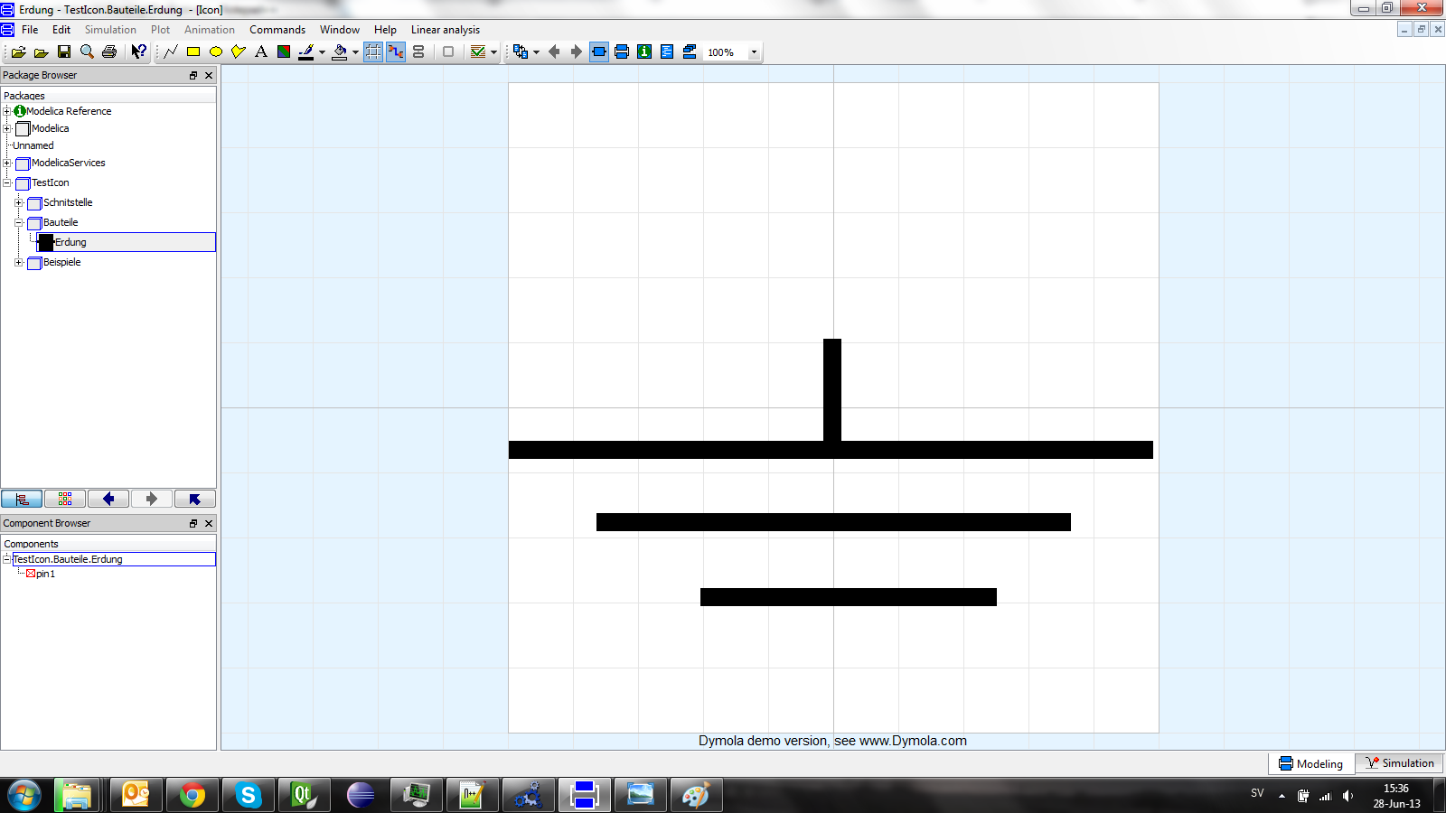
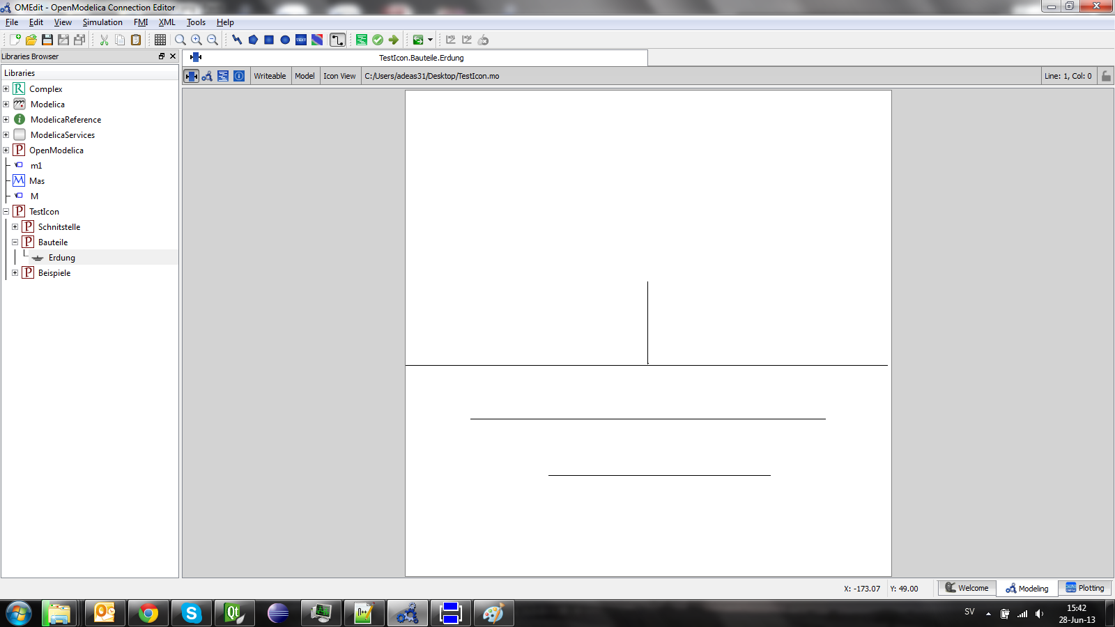
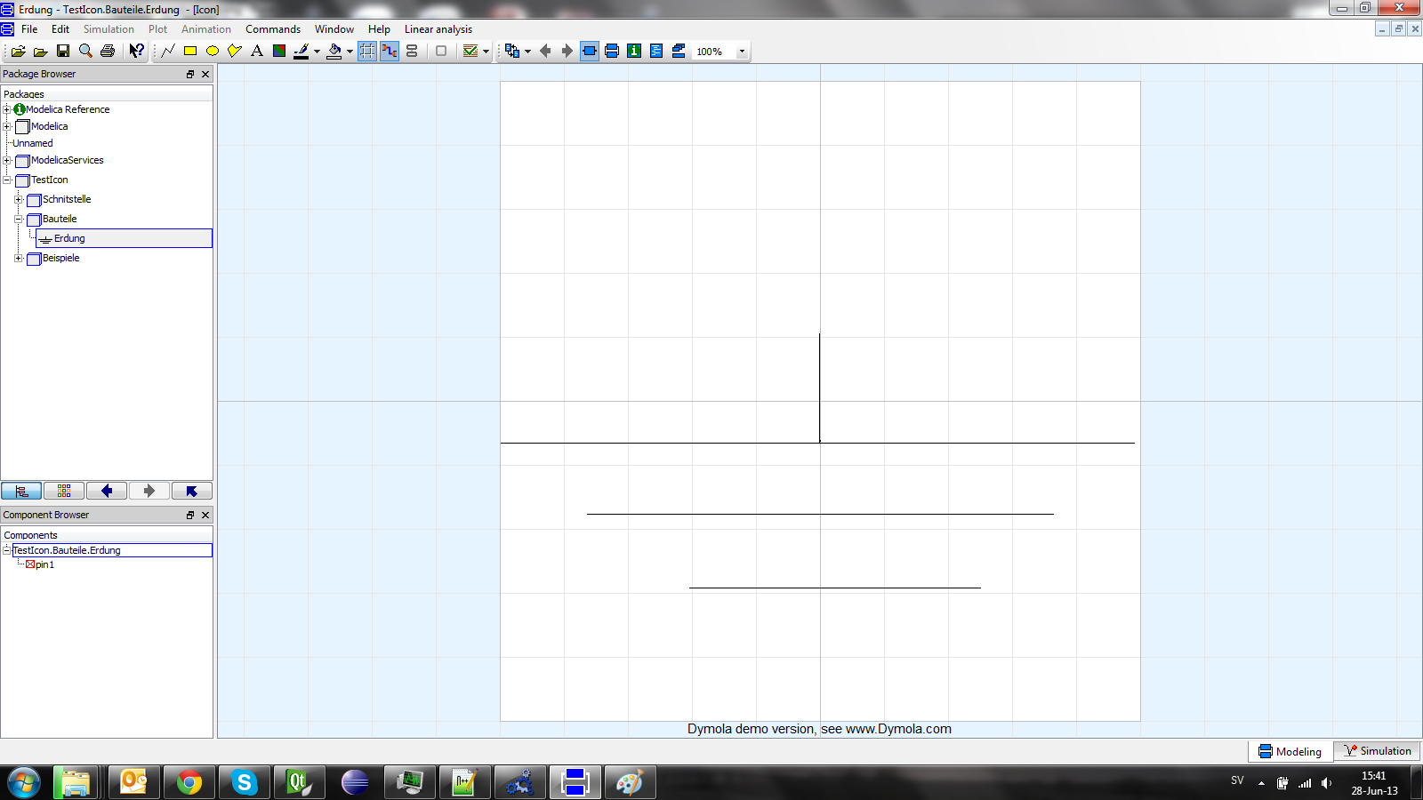
OK. It looks to me more like a Qt issue. Seems like Qt can't handle the scaling of shapes with high pen thickness. Even Dymola can't handle it. I have attached the images of Dymola and OMEdit with original model you posted and then I modified the Line thickness in the model. The modified model is,
package TestIcon
  package Schnitstelle
    connector Pin
      Real v;
      flow Real i;
      annotation(Diagram(coordinateSystem(extent = {{-100,-100},{100,100}}, preserveAspectRatio = true, initialScale = 0.1, grid = {2,2})), Icon(coordinateSystem(extent = {{-100,-100},{100,100}}, preserveAspectRatio = true, initialScale = 0.1, grid = {2,2}), graphics = {Rectangle(origin = {0,5.46022}, fillColor = {255,0,0}, fillPattern = FillPattern.Solid, extent = {{-99.5319,94.6958},{100.156,-105.616}})}));
    end Pin;
    connector NPin
      Real v;
      flow Real i;
      annotation(Icon(coordinateSystem(extent = {{-100,-100},{100,100}}, preserveAspectRatio = true, initialScale = 0.1, grid = {2,2}), graphics = {Rectangle(origin = {-15.7566,25.429}, fillColor = {0,0,255}, fillPattern = FillPattern.Solid, extent = {{-84.0874,74.415},{115.601,-125.897}})}));
    end NPin;
    annotation(Icon(coordinateSystem(extent = {{-100,-100},{100,100}}, preserveAspectRatio = true, initialScale = 0.1, grid = {2,2})), Diagram(coordinateSystem(extent = {{-100,-100},{100,100}}, preserveAspectRatio = true, initialScale = 0.1, grid = {2,2})));
  end Schnitstelle;
  package Bauteile
    model Erdung
      Pruefung.Schnittstelle.Pin pin1 annotation(Placement(visible = true, transformation(origin = {-14.741,40.6375}, extent = {{-10,-10},{10,10}}, rotation = 0), iconTransformation(origin = {-0.438261,34.3825}, extent = {{-11.1155,-11.1155},{11.1155,11.1155}}, rotation = 0)));
    equation
      pin1.v = 0;
      annotation(Diagram(coordinateSystem(extent = {{-100,-100},{100,100}}, preserveAspectRatio = true, initialScale = 0.1, grid = {2,2})), Icon(coordinateSystem(extent = {{-100,-100},{100,100}}, preserveAspectRatio = true, initialScale = 0.1, grid = {2,2}), graphics = {Line(origin = {20.3187,-17.9283}, points = {{-119.92,4.78088},{78.0876,4.78088}}, thickness = 0.25),Line(origin = {-5.0996,-40.1594}, points = {{-67.7288,4.78088},{78.0876,4.78088}}, thickness = 0.25),Line(origin = {-27.7291,-63.1873}, points = {{-13.1471,4.78088},{78.0876,4.78088}}, thickness = 0.25),Line(origin = {0.605578,-11.7529}, points = {{-1.00398,32.8684},{-1.00398,-0.996111},{-0.605578,-0.597701}}, thickness = 0.25)}));
    end Erdung;
    annotation(Icon(coordinateSystem(extent = {{-100,-100},{100,100}}, preserveAspectRatio = true, initialScale = 0.1, grid = {2,2})), Diagram(coordinateSystem(extent = {{-100,-100},{100,100}}, preserveAspectRatio = true, initialScale = 0.1, grid = {2,2})));
  end Bauteile;
  package Beispiele
    model Test
      TestIcon.Bauteile.Erdung erdung1 annotation(Placement(visible = true, transformation(origin = {-39.4366,-44.1315}, extent = {{-10,-10},{10,10}}, rotation = 0)));
      Modelica.Electrical.Analog.Sources.SineVoltage sinevoltage1(V = 5, freqHz = 10) annotation(Placement(visible = true, transformation(origin = {-65.2582,21.5962}, extent = {{-10,-10},{10,10}}, rotation = -90)));
      Modelica.Electrical.Analog.Basic.Resistor resistor1(R = 470) annotation(Placement(visible = true, transformation(origin = {22.0657,19.2488}, extent = {{-10,-10},{10,10}}, rotation = -90)));
    equation
      connect(sinevoltage1.n,erdung1.pin1) annotation(Line(points = {{-65.2582,11.5962},{-65.2582,-9.38967},{-39.4366,-9.38967},{-39.4366,-40.8451},{-39.4366,-40.8451}}));
      connect(resistor1.n,sinevoltage1.n) annotation(Line(points = {{22.0657,9.24883},{22.0657,-8.92019},{-65.2582,-8.92019},{-65.2582,10.7981},{-65.2582,10.7981}}));
      connect(sinevoltage1.p,resistor1.p) annotation(Line(points = {{-65.2582,31.5962},{-65.2582,45.0704},{22.0657,45.0704},{22.0657,28.6385},{22.0657,28.6385}}));
      annotation(Icon(coordinateSystem(extent = {{-100,-100},{100,100}}, preserveAspectRatio = true, initialScale = 0.1, grid = {2,2})), Diagram(coordinateSystem(extent = {{-100,-100},{100,100}}, preserveAspectRatio = true, initialScale = 0.1, grid = {2,2})));
    end Test;
    annotation(Icon(coordinateSystem(extent = {{-100,-100},{100,100}}, preserveAspectRatio = true, initialScale = 0.1, grid = {2,2})), Diagram(coordinateSystem(extent = {{-100,-100},{100,100}}, preserveAspectRatio = true, initialScale = 0.1, grid = {2,2})));
  end Beispiele;
  annotation(Icon(coordinateSystem(extent = {{-100,-100},{100,100}}, preserveAspectRatio = true, initialScale = 0.1, grid = {2,2})), Diagram(coordinateSystem(extent = {{-100,-100},{100,100}}, preserveAspectRatio = true, initialScale = 0.1, grid = {2,2})));
end TestIcon;
I will try to investigate a bit more about it but for now i suggest using pens with low thickness value.
comment:9 by , 13 years ago
| Milestone: | 2.0.0 → 1.9.0 |
|---|
BatchModify: Updating milestone since this ticket was closed in time for the 1.9.0 release
Is it possible for you to share your library OR atleast the piece of code that we can use for testing?